
H2 - fuel of the future
***_Hydrogen Guide by async_ ***
http://asyncbrain.baf.cz |
jense@seznam.cz
Note that this document is a mixture of the web sites' texts with my additional info.
Why H2 as basic element of global solution of powering?
General problems with hydrogen production, handling and comercialization:
| izotopes | 11H, 21H (deuterium D), 31H (tritium T) |
| molecule | H-H |
| melting temperature @100kPa | -259.14 degC |
| boiling temperature @100kPa | -252.8 degC |
| critical temp&pressure | -239.92 degC @ 1.297MPa |
| specific heat | 14.189kJ.Kg^-1.K^-1 (approx 3.4x higher than water) |
| explosive mixture with oxygen | 6 - 95 per cent H2 in O2 |
| ignition temperature of H2+O2 mixture | ~450 degC |
| amout of hydrogen on Earth of the whole mass | ~0.9 per cent |


This method is based on decomposition of water vapour using coke in the temperature of 1200 degC to hydrous gas (CO+H2) and then converse the mixture of this gas with water vapour on Fe2O3 and Cr2O3 catalyst in the temperature of 300-450 deg C. Emitted CO2 is absorbed by water under increased pressure (10-30 Mpa) and NaOH absorbs residues.C + H2O - > CO + H2
The biggest disadvantage of this method is the necessity of achieving so high temperature what causes an immense loss of the energy.
C + H2 + H2O -> CO2 + 2H2
This method is composed of two steps. The first step is to expose natural gas to high-temperature steam to separate hydrogen from carbon atoms in natural gas (CH4), additionally carbon monoxide (CO) and carbon dioxide (CO2) are produced. The second step is to convert the carbon monoxide with steam to produce supplementary hydrogen and carbon dioxide.CH4 + H2O -> CO + 3H2
CO + H2O -> CO2 + H2Hydrogen produced by this method is not used as a fuel but in manufacture of fertilisers and chemicals and to upgrade the quality of petroleum products. Nowadays this is the most effective way of gaining hydrogen but it uses fossil fuels both in manufacturing process and as the heat source, what is a great disadvantage of this method.
Ad.
3H2 + CO named as "syngas" It's used ceramic membrane Sr-Fe-Co-O @ 900C to select gases CO, H2.
CO + H2O -> H2 + CO2 (water gas shift reactor WGSR)This generates 0.3-0.4m^3 CO2 / 1m^3 H2.


Links:
http://www.wangtec.com/h2info.html
http://www.et.anl.gov/sections/ceramics/research/ceram_mem.html
Hydrogen is produced by this method due to increase the octane number of gasoline in the process of dehydrogenation of hydrocarbons.C6H12 -> C6H6 + 3H2 C6H14 -> C6H6 + 4H2
CH4 + 1/2 O2 = 2H2 + CO (1250 degC)
CH3OH + H2O = 3H2 + CO2 (300 degC)
2 NH3 = 3 H2 + N2 (300 degC)
- direct conversion CH4 -> C + 2H2
- no water, no oxygen used => NO greenhouse gases emissions
- CH4 is bubbled through molten metal (Pb or alloys). Solid carbon is separeted by different metal and carbon density. Carbon "waste" could be used for carbon composites fabrication.
- heat source: nuclear reactors (higher conversion efficiency), solar or CH4,H2 combustion
nuclear DCP: http://www.cmt.anl.gov/science-technology/basicsci/hydrogen.shtml
This method use the electricity to split water into hydrogen and oxygen.2H2O + 2e -> H2 + 2OH (on the cathode)
To gain hydrogen by means of this method we have to provide more energy in form of electricity (4.3 to 5.7 kWh/m3) than we are able to achieve from combustion of hydrogen (3 kWh/m 3 ). There are some proposals of using other sources of energy like nuclear energy or the energy of sun and wind to perform electrolysis but also these opportunities faces some problems.
2OH - >H2O + 1/2 O2 + 2e (on the anode)
H2O + electricity -> H2 + 1/2 O2 (globally)Ad. An improved electrolysis technology:
* The Hot Elly method, based on hot electrolysis of water vapour at the temperature 900 degC. There is used solid electrolyte (ceramics) ZrO2 there. Efficiency ~85per cent.* The Solid Polymer Electrolyte (SPE) see picture:

Thermal decomposition of water is occurring only in the temperature above 5177 o C (practically imposible) which is practically impossible to achieve nowadays. However, execution of decomposition in two cycles allows decreasing this temperature to 3067 o C:CO + H2O > H2 + CO2 (477 degC)
Profitability of this method is strictly connected with possessing the cheap source of carbon monoxide (for instance gasification or incomplete combustion of coal) because the full cycle is too expensive in realisation, caused by the cost of achieving the temperature needed to decompose CO2.
CO2 > CO + 1 O2 (3067 degC)Ad. But there are a lot of termochemical cycles which enables "low" temperature operations as:
Please see details @:
Ispra Mark 2 (1972) T 100C: Na2O.MnO2 + H2O = 2 NaOH + MnO2
T 487C: 4 MnO2 = 2 Mn2O3 + O2
T 800C: Mn2O3 + 4 NaOH = 2 Na2O.MnO2 + H2 + H2OIspra Mark 7B T 1000C: 2Fe2 O3 + 6Cl2 (g) = 4FeCl3 + 3O2 (g)
T 420C: 2FeCl3 = Cl2 (g) + 2FeCl2
T 650C: 3FeCl2 + 4H2 O = Fe3 O4 + 6HCl + H2 (g)
T 350C: 4Fe3 O4 + O2 (g) = 6Fe2O3
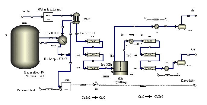
T 400C: 4HCl + O2 (g) = 2Cl2 (g) + 2H2OUniversity of Tokyo Cycle #3 (UT- 3) (nuclear heat water-splitting) 1) Water splitting with HBr formation (1000 K):
CaBr2 + H2O = CaO + 2 HBr
2) Oxygen formation (823 K)
CaO + Br2 = CaBr2 + 1/2 O2
3) Bromine regeneration (493 K)
Fe3O4 + 8 HBr = 3 FeBr 2 + 4 H2O + Br2
4) Hydrogen formation from FeBr 2 (923 K)
3 FeBr2 + 4 H2O = Fe3O4 +6 HBr + H2Modified Calcium-Bromine Cycle (nuclear heat water-splitting) [1] Water splitting with HBr formation (1000 K):
CaBr2 + H2O = CaO + 2 HBr
[2] Oxygen formation (823 K)
CaO + Br2 = CaBr2 + 1/2 O2
[3] Bromine regeneration (non- thermal plasma)
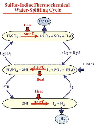
2 HBr + plasma = H2 + Br2GA Sulfur-Iodine (nuclear heat water-splitting) T 850C: 2 H2SO4 = 2 SO2 + 2H2O + O2
T 300C: 2 HI = I2 + H2
T 100C: I2 + SO2 + 2 H2O = 2HI + H2SO4INITIAL SCREENING OF THERMOCHEMICAL WATER-SPLITTING CYCLES FOR HIGH EFFICIENCY GENERATION OF HYDROGEN FUELS USING NUCLEAR POWER: http://web.gat.com/pubs-ext/miscpubs/A23373.pdf
"Nuclear Hydrogen" using calcium-bromine or sulphur-iodine water splitting cycle ( L. C. Brown, G. E. Besenbruch, General Atomics J. E. Funk, University of Kentucky A.C. Marshall, P.S. Pickard, S.K. Showalter, Sandia National Laboratories):
http://www.eren.doe.gov/hydrogen/pdfs/32405d.pdf


"Nuclear Hydrogen" using calcium-bromine water splitting cycle (Richard D. Doctor, Argonne National Labs): http://web.gat.com/hydrogen/images/pdf%20files/doctor_ca_br_h2.pdf
Schematic:
The Shulten method is based on decomposition of water composed of four steps of closed cycle. The highest temperature needed to perform this method is 927 degC which can be obtained without any trouble. During this method a cycle of reactions between methane (CH4), water (H2O), carbon monoxide (CO) and some others substances occurs. The efficiency of whole cycle is 40-45per cent which is quite satisfying.
Transforming solar energy in the solar cells into electricity, which flew through the cover made of rhodium, molybdenum, wolfram and presently porphyrynium compounds (nearing in structure to chlorophyll) decompose water not electrolytic but catalytic.The photocatalytic process uses semiconducting catalysts or electrodes in a photoreactor to convert optical energy into chemical energy. A semiconductor surface is used to both absorb solar energy and to act as an electrode for splitting water. This technology is still at an early stage of development. The most stable photoelectrode is TiO2; however, this material has a conversion efficiency of less than 1%. New materials, which require no external electricity should be studied. In order to reduce corrosion, ultra thin layers of protective material on the semiconducting surface could be coated. Investigations also can be directed toward in the areas of low cost systems, multiple layers of organic dyes and thin film semiconductors.
The Hydrogen produced is very pure and can feed electronic fuel cells.In a single step, solar energy is collected and transformed into electric charges, which split water at two separate points (the anode and the cathode) releasing two separate gas streams of oxygen and hydrogen respectively. Thus the need for gas separation is avoided.The front cell intercepts at the blue end of the spectrum, using a partially transparent crystalline thin film. The remaining part of the spectrum of white light is intercepted by a second cell (placed behind the first one), thus increasing the efficiency of the device beyond that of a single cell unit.


see details @:http://www.h2spc.com
And PHOTOPRODUCTION OF HYDROGEN IN NON OXYGEN-EVOLVING SYSTEMS@ http://www.h2net.org.uk/Pubs/Pubs.htm#Reports_
* Transforming solar energy in the solar kiln of 1000 kW power, with parabolic mirrors into heat (to 4000 K) and using obtained heat to thermal decomposition of water (water thermolysis 2500 degC)
* Bacteria usage for the anaerobic decomposition of biomass.Fermentative H2 production:C6H12O6 + 2 H2O = CH3COOH + 2 CO2 + 4 H2
- yield: 0.5 m3 H2 / kg carbohydrate
- thermodynamically unfavourable as H2 concentartion risesUnit cost of fermentative H 2 from sugar cane 0.26 DM/kWh (Tanisho,1996).
- property of many species of bacteria, particularly Clostridia
- dark, anaerobic process
- carbohydrates are favoured substrate
- involves hydrogenase
- produces CO2
- maximum H2 yield with acetate as fermentation product
Unit cost for wind-powered electrolysis plants 0.5-0.2 DM/kWh (Dutton et al., 2000)download PDF @:http://www.h2net.org.uk/Pubs/Pubs.htm#Reports_
* Photoreduction of water by means of microorganisms.Cyanobacteria and green algae
- use water as substrate, so O2 produced, which must be separated as O2 inhibits H2 production by nitrogenase
- H2 production also inhibited by N2 so an argon, low-pressure or nitrogen-fixing environment must be provided
- efficiency (defined as energy yield from burning H2 per unit input light energy) is currently < 1%, though the economically desirable level of ~ 10% is theoretically achievable.
- of the chemical potential energy captured as hydrogen-containing compound, 75% is in the form of NH3 and 25% as H2
by Dr. Krishna Rao : Photobiological hydrogen productionplease see literature: Biohydrogen - Green Alga & photo-bioreactor:
http://www.ornl.gov/divisions/ctd/march2.htmRenewable energy sources (PDF): aes.pdf - eBook: Alternative Energy Sources by Jakub Pusz
Biohydrogen production pathways (indirect via photosysthesis and direct via alga mutant):
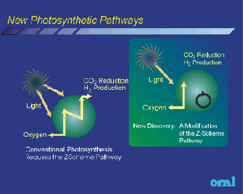
Green Alga:
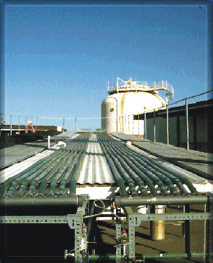
Bioreactor:
see also DERA's concepts: http://www.h2net.org.uk/PDFs/Stor2000/H2nettalk_Nov00.pdf
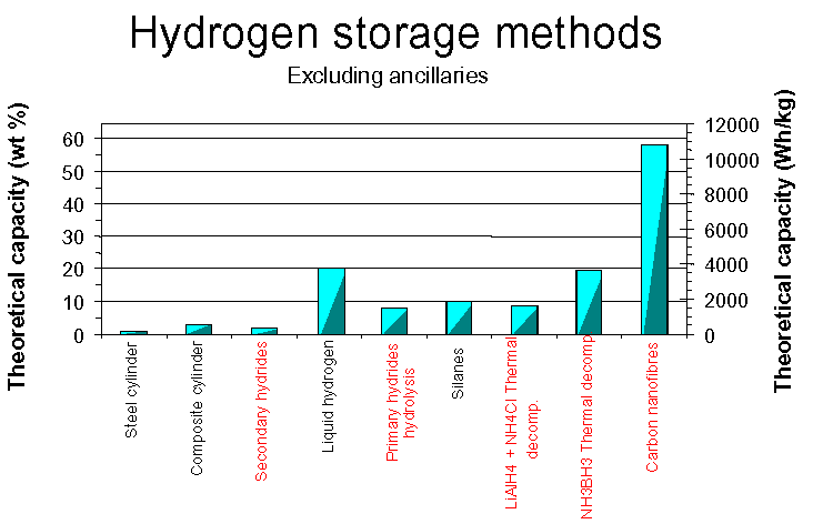
One of the greatest problems connected with hydrogen was the method of its storage. The very high explosiveness of this gas, forced scientists to work intensively on developing new safe way of its lying in. We can distinguish the following ways of hydrogen storage:
This method may be applied only in stationary usage because of the danger of explosion and high weight of the vessel. This process requires energy to accomplish and the space that the compressed gas occupies is usually quite large resulting in a lower energy density when compared to a traditional gasoline tank. A hydrogen gas tank that contained a store of energy equivalent to a gasoline tank would be more than 3,000 times bigger than the gasoline tank. Hydrogen can be compressed into high-pressure tanks where each additional cubic foot compressed into the same space requires another atmosphere of pressure of 14.7 psi. High-pressure tanks achieve 6,000 psi, and therefore must be periodically tested and inspected to ensure their safety.Traditional steel cylinders:
Composite cylinders:
- heavy, typically <1 wt % (186 Wh/kg)
- carbon fibre wrapped over an inner Al or thermoplastic liner
- much lighter than steel cylinders, ca. 3 wt % (560 Wh/kg)
- Ultra high pressure composite cylinders, ca. 10 wt% (1860 Wh/kg)
- LLNL/IMPCO tested 11 wt % cylinder @ 350 bar (2100 Wh/kg)
- Bulky storage method
- User resistance to high pressure cylinders
Composite cyclinders (DERA): Vessels (Air Products PLC, Hydrogen Production Workshop University of Glamorgan 14 February 2001):


Liquid Hydrogen Hydrogen does exist in a liquid state, but only at extremely cold temperatures. Liquid hydrogen typically has to be stored at 20K or -253C. The temperature requirements for liquid hydrogen storage necessitate expending energy to compress and chill the hydrogen into its liquid state. The cooling and compressing process requires energy, resulting in a net loss of about 30% of the energy that the liquid hydrogen is storing. The storage tanks are insulated, to preserve temperature, and reinforced to store the liquid hydrogen under pressure.Combine the energy required for the process to get hydrogen into its liquid state and the tanks required to sustain the storage pressure and temperature and liquid hydrogen storage becomes very expensive comparative to other methods. Research in the field of liquid hydrogen storage centers around the development of composite tank materials, resulting in lighter, stronger tanks, and improved methods for liquefying hydrogen.
Liquid hydrogen storage/transport (Air Products PLC, Hydrogen Production Workshop University of Glamorgan 14 February 2001):

This is the technical term for the hydrogen being stored in the fossil fuels that are common in today's society. Whenever gasoline, natural gas methanol, etc.. is utilized as the source for hydrogen, the fossil fuel requires reforming. The reforming process removes the hydrogen from the original fossil fuel. The reformed hydrogen is then cleaned of excess carbon monoxide, which can poison certain types of fuel cells, and utilized by the fuel cell. Reformers are currently in the beta stage of their testing with many companies having operating prototypes in the field. See hydrogen production>Steam methane reforming (SMR) @Hydrogen production section
It's similar to Liquid Carrier Storage. Many of these compounds are utilized as a hydrogen storage method. The hydrogen is combined in a chemical reaction that creates a stable compound containing the hydrogen. A second reaction occurs that releases the hydrogen, which is collected and utilized by a fuel cell. The exact reaction employed varies from storage compound to storage compound. Some examples of various techniques include ammonia cracking, partial oxidation, methanol cracking, etc. These methods eliminate the need for a storage unit for the hydrogen produced, where the hydrogen is produced on demand. The best weight percent efficiency for secondary storage is approximately 20 % for BH3NH3, for which hydrogen release is achieved by thermal decomposition at 100-300 degC.DERA's info:
- Hydrolysis (reaction with water)
- Primary hydrides
- e.g. LiH, LiBH 4 , NaBH 4- Thermolysis (decomposition by heat)
- NH4X + MH
- NH3BH3
Metal hydrides are specific combinations of metallic alloys that act similar to a sponge soaking up water. Metal hydrides posses the unique ability to absorb hydrogen and release it later, either at room temperature or through heating of the tank. The total amount of hydrogen absorbed is generally 1% - 2% of the total weight of the tank. Some metal hydrides are capable of storing 5% - 7% of their own weight, but only when heated to temperatures of 2500 C or higher. The percentage of gas absorbed to volume of the metal is still relatively low, but hydrides offer a valuable solution to hydrogen storage.
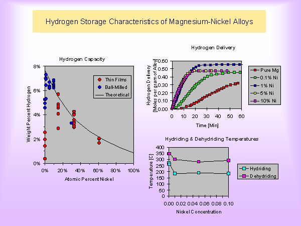
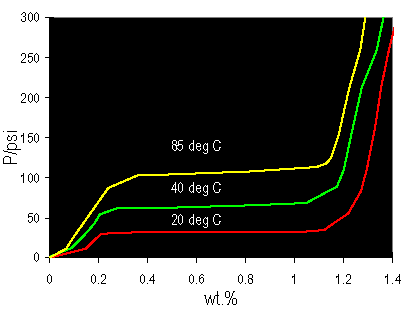
Metal hydride sorption and desorption formulae:
M + xH2 <-> MH2x Features:
- Good volumetric performance: theoretical 100 g/L,1860 Wh/L.
- Poorer gravimetric performance: theoretical 1-2 wt %, 186-370 Wh/kg.
- Desorption endothermic - requires heat.
- H2 stored at constant P - safe storage.
Metal hydrides offer the advantages of safely delivering hydrogen at a constant pressure. The life of a metal hydride storage tank is directly related to the purity of the hydrogen it is storing. The alloys act as a sponge, which absorbs hydrogen, but it also absorbs any impurities introduced into the tank by the hydrogen. The result is the hydrogen released from the tank is extremely pure, but the tank's lifetime and ability to store hydrogen is reduced as the impurities are left behind and fill the spaces in the metal that the hydrogen once occupied. H2 could be purified via ceramic membranes: http://www.et.anl.gov/sections/ceramics/research/ceram_mem.html
One volumetric unit of lithium during the reaction with hydrogen is able to absorb about 1600 units of this gas. A significant improvement in storage efficiency is required for transport applications, which in the case of a typical car has a fuel requirement of ~ 1 kg of H2 per 100 km travelled.
Gravimetric curves:
Links:
buy your own metal-hydride tank (commerce): http://www.fuelcellstore.com/products/index/hydrogen_storage.html
Polymer-dispersed metal hydrides (PDMH) http://www.eren.doe.gov/hydrogen/pdfs/30535aq.pdf
http://www.materiale.kemi.dtu.dk/hydrid/
http://mstd.nrl.navy.mil/6320/6323/HydrogenStorage.html

A powder of an alloy of lanthanum with cobalt and samarium with nickel is able to absorb under the pressure of 0.4 MPa (4 atm) such amount of hydrogen, which was able to store in the same vessel but under the pressure of 100 MPa (1000 atm).
Tiny hollow glass spheres can be used to safely store hydrogen. The glass spheres are warmed, increasing the permeability of their walls, and filled by being immersed in high-pressure hydrogen gas. The spheres are then cooled, locking the hydrogen inside of the glass balls. A subsequent increase in temperature will release the hydrogen trapped in the spheres. Microspheres have the potential to be very safe, resist contamination, and contain hydrogen at a low pressure increasing the margin of safety.DERA's info:
- W.J.Schaffer have claimed capacities of > 10 % - pressures of 10,000 psi
- permeable to H 2 at high temperatures (> 200 o C)
- impermeable at room temperature
- spheres produced by a single drop process
- slow, expensive- DERA tested commercial glass microspheres - average particle size 6 - 75 mm
- capacity of 0.9 wt % @ 1000 psi
- would equal 5.9 % @ 10,000 psi
- unfortunately most spheres broke > 3000 psi
- Conclusions - Commercial spheres not suited to H2 storage
- Need perfect spheres, no defectsMicrospheres:

keyword: fullerenes

Carbon nanotubes are microscopic tubes of carbon, two nanometers (billionths of a meter) across, that store hydrogen in microscopic pores on the tubes and within the tube structures. Similar to metal hydrides in their mechanism for storing and releasing hydrogen, the advantage of carbon nanotubes is the amount of hydrogen they are able to store. Carbon nanotubes are capable of storing anywhere from 4.2% - to 65% of their own weight in hydrogen. A novel mechanism of hydrogen storage in carbon nanotubes is proposed by using the density functional calculations. Several key intermediate states are identified for hydrogen adsorption. Up to the coverage of 1.0, hydrogen atoms chemisorb on the nanotube wall with either an arch type or a zigzag type. Then, hydrogen can be further stored inside the nanotubes at higher coverage as a molecular form. Hydrogen atoms can be inserted into the nanotubes through the tube wall via flip-in and/or kick-in mechanism with activation barriers of 1.5 and 2.0 eV, respectively. In the hydrogen extraction process, hydrogen molecules inside a nanotube firstly dissociates onto the inner wall with an activation barrier of 1.6 eV. Secondly, hydrogen atoms at the interior of the tube wall are further extracted to the outer wall by the flip-out mechanism with an activation barrier of 2.0 eV.
Our studies of carbon nano-material adsorptive properties for hydrogen, containing ~ 70 w/w % of SWNTs, showed that the materials were capable of absorbing ~ 3.5 w/w % of hydrogen at 100 atm at room temperature and evolving hydrogen at pressures drop down to 1 atm. Analysis of scientific publications shows that the experimental data are often contradictory, however, a comparative analysis of the systems for hydrogen storage on the whole shows that the parameters of carbon nano-materials are close to those required for motor transport. The reason of the parameter discrepancy is the lack of reliable methods for carbon nano-materials certification, namely, the content of SWNT and MWNT, the content of open tubes and the distribution in diameter. Additionally, residual catalysts affect hydrogen sorption.
Single-walled carbon nanotubes (SWNT) hold great promises as hydrogen storage medium. Their unique architecture makes them the best carbon-based adsorbent for hydrogen. It has been predicted theoretically that gravimetric density of up to 16 weight percent of H2 and volumetric density of 160 kg/m3 of H2 can be stored in (10,10) SWNT. This value exceeds greatly the US Department of Energy's energy density target of 6.5 weight percent and 62 kg/m3 for an economically viable vehicular hydrogen storage medium. This value has never been obtained experimentally in a reproducible way, creating much controversy in the field. This is because of the lack of controls in the synthesis of SWNT, the lack of understanding of the effects of chemical modifications through the purification processes, and the lack of understanding of how molecular hydrogen interacts with SWNT.
ENER1 has the necessary experience and expertise to carry out studies of electrochemical intercalation of Li and other alkali metals into carbon nano-materials. According to predictions, carbon nanotubes intercalated by Li can demonstrate high electrochemical capacity (up to 640 mAh/g) in the first cycles, though capacity can decrease in cycling.
==
Carbon nanotubes in their single-walled form are typically around 1.3 nm in diameter and are on the order of 100um in length. They occur in three different structural forms, with different diameters, the proportions of which are difficult to control in synthesis. The three principal production methods are laser vaporisation of a Ni/Co-doped graphite target, DC arc using a Ni/Y-doped graphite anode, and vapour growth using Fe, Co and Ni catalyst particles with a hydrocarbon feedstock at 1000 degC. Of these methods, the DC arc has better scalability. The storage potential of nanotubes is in the range of 2 - 14 hydrogen weight percent, with claims of up to 72 weight percent made for graphitic nanofibres. Advantages of carbon nanostructures as storage media include their low mass density, chemical stability (up to 900 degC in an inert atmosphere)and fast sorption kinetics compared to metal hydrides, owing to the hydrogen uptake being a surface rather than a bulk process. At present they suffer from the disadvantages of being very expensive to produce in practically useful quantities, difficulties in purification of raw nanofibre material, and the need for low temperatures or high pressures to achieve high levels of storage.DERA's info:
- Store up to 10 wt % H 2
- Require either:
- high pressure (>100 bar)
- low temperature (< -100 o C)
- Different forms
- MWNT
- SWNT
- capped
- uncapped
- 1-10 nm diameter
Links:
http://www.eren.doe.gov/hydrogen/pdfs/30535an.pdf
http://www.foresight.org/Conferences/MNT9/Abstracts/Simard/
http://www.nanotube.org/abs/LeeSM.html
http://www.kjemi.uio.no/ecssc8/Final-pdf/OH5.pdf
http://www.ener1.com/b_storage.shtml
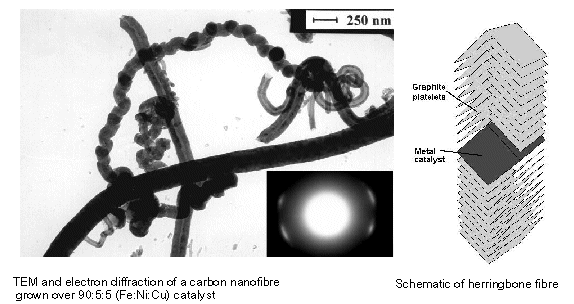
DERA's info:
- Developed by Northeastern University
- Consist of stacked graphite plates
- Thin fibres of 5-100 nm diameter and 5-100mm length
- Spacing between planes (0.34 nm) perfect for H2 (H2 diameter of 0.29 nm)
- Potentially store over 50 wt % H 2 (9300 Wh/kg)
- Room temperature storage
- High pressure required

A fuel cell produces electricity by converting the chemical energy of fuel directly to power in a controlled chemical reaction - without combustion and without moving parts. Fuel cells are therefore inherently ultra clean, highly efficient and reliable. The performance and structure of the fuel cell is explained below:
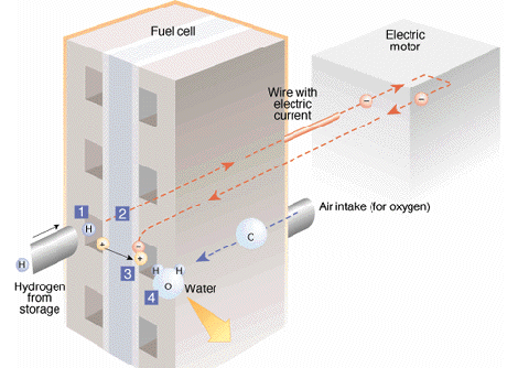
1. Hydrogen molecules, which consist of single proton circled by a single electron, enter the fuel cell and come in contact with platinum. This catalyst helps to split the hydrogen into positively charged ions and negatively charged electrons.see author's pages: http://www.pg.gda.pl/chem/Katedry/Maszyny/FC/FUEL_CELLS/fcns.htm
2. An "electrolyte", a special membrane or a substance screens out the electrons. These electrons, which create an electric current, are sent through the wire to power the vehicle's electric motor. Then they return to the fuel cell.
3. The ions are able to pass through the electrolyte.
4. In the third portion of the fuel cell, the hydrogen ions, the electrons and oxygen combine to make water. Water is continuously removed from the fuel cell as the ions and electrons keep flowing through the cell. It is the cell's only waste product.The process works like this:
Anode: 2 H2 = 4H + + 4e -
Cathode: 4e - + 4H + + O2 = 2H2O
Overall: 2H2 + O2 = 2H2O
It uses liquid electrolyte in the form of ortho-phosphoric acid - H3PO4 and platinum as a catalyst. The electrolyte is placed between porous electrodes made of graphite, in Teflonated casing, filled with Silicone Carbide (SiC). The role of SiC is to keep the electrolyte in the proper place, avoiding its leakage. The oxidizer (O2 in this case - may be taken directly from air decreasing the efficiency only to the 36-42%) is reduced. The water vapor is evolved to the excess of air or O2 therefore it may be easily disposed from the fuel cell, avoiding the same the dilution of the electrolyte. Otherwise, it may lead to the decrease of the ionic conductivity of electrolyte and dropping the system efficiency. The power density of PAFC is equal to 1.7 kW/m2 - 1.9 kW/m2 of the FC active surface. PAFC has high sensitivity of the electrolyte toward overheating. At the temperature 210oC the phosphoric acid decomposes, what demands usage of advanced cooling systems. Electrolyte diffusion through the electrodes and escapes with the overflowing gases, what demands refilling it just after a few hours of operation. It causes a very troublesome maintenance.
This kind of fuel cells uses molten lithium carbonates (Li2CO3) and molten potassium carbonates (K2CO3) as an electrolyte. The research on MCFC has started in 1960's when the idea of applying hard coal as a fuel in a fuel cell appeared. Molten electrolyte working at the temperature of 650oC is mixed with a chemically inactive porous ceramic material (for instance LiAlO2). The anode is made of porous nickel sinter enriched with chromium to avoid deformation during operation. The cathode is formed of nickel oxide and lithium sinter. The high working temperature enables to use Ni catalyst instead of more noble metals that decreases the costs. MCFC can run on carbon monoxide, formed for instance during incomplete combustion of coal, or hydrogen. In case of the usage of the latter fuel, the following reaction on the anode occurs: H2 + CO3 2- = H2O + CO2 + 2e- Due to this reaction, the electrons flow through the external circuit and to the fuel inlet water vapor and carbon dioxide evolves. The CO2 should be gathered because it must be used in the further process of carbonate ion recombination on the cathode. The CO2 may be gathered by combustion in the air of the fuel-hydrogen-residue. In the case if the CO2 will not be separated from H2 and together will be supplied to the oxidizer, an explosion will occur (autoignition temperature of H2 is equal to 565.56 degC). In the future there is planned to use some membrane separators. In the case of using carbon monoxide as a fuel, the following reaction occurs on the anode: CO + CO32- = 2CO2 + 2e- Due to this reaction carbon dioxide is evolved, then, like in the case of H2 as a fuel, must be gathered and used in the cathodic processes: 2CO2 + O2 + 4e- -> 2CO32- As the end process of MCFC operation, carbonate anions are formed. This type of fuel cells has the efficiency equal to 50-60% and may use some other fuels that make them a bit superior over PAFC. Thanks to the high working temperature, the evolving heat may be used to increase the total electrical efficiency of the whole system. It may be done by using the excess of heat in the traditional systems, where steam rotates turbines producing mechanical energy that is transformed into electricity later on. There is a need of using high-speed flowing gas as a cooler that produces considerable amount of noise. MCFC has high sensitivity towards changes of electrolyte temperature. For instance, cooling electrolyte from 650degC to 600degC results in such a high increase of ionic conductivity resistance that the output voltage falls down by 15%. Last disadvantage of MCFC is high corrosion of cathode.
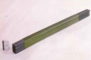
This fuel cell uses ceramic material made of zirconium oxide (ZrO2) enriched with yttrium (Y) as an electrolyte that at the temperature of 1000degC is a perfect oxygen anion conductor. Owing to applying solid electrolyte almost no corrosion of electrodes occurs and there is no need to use a porous material to keep the electrolyte at the proper place. Moreover, there is no loss of electrolyte by evaporation or diffusion through the electrodes. The anode is made of porous nickel or zirconium sinter and the cathode is magnesium mixed with lanthanum manganese. The Westinghouse company made the SOFC's cathode from a small pipe made of zirconium sinter covered with zirconium oxide (ZrO2) lagged with anode. The oxidizer (air or O2) flows through the cathode-pipe and all the system is rinsed with fuel. The fuel may be hydrogen, carbon monoxide or methane. During the operation the following anodic reactions for specific fuels occur:
The reaction for hydrogen fuel: H2 + O2- = H2O + 2e-
The reaction for carbon monoxide fuel: CO + O2- = CO2 + 2e-
The reaction for methane as a fuel: CH4 + 4O2- -> 2H2O + CO2 + 8e-
On the cathode the following reaction occurs: O2 + 4e- ->2O2.
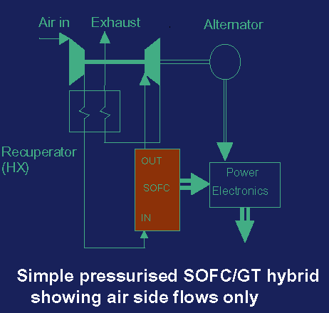
Data from 06.2001 says that SOFC has the power density of 1.5 kW/m2 of active fuel cell surface at the voltage of 0.6V and works with the efficiency of 40-50%. However, the increase of the fuel pressure may lift it up to 60%. Due to high working temperature, the evolved heat may be used to transform water into steam that rotates turbines producing mechanical energy transformed into electricity later on. Moreover, this kind of fuel cell is more resistive towards sulfur impurities of the fuel than other fuel cells that make it possible to apply easily in houses using the gas from domestic cookers. SOFC is sensitive to temperature changes. The decrease of 100oC diminishes the electrical efficiency by 12%. Very high working temperature that demands usage of very specific materials that are resistive to such severe conditions. That makes the system expensive and unable to miniaturize. Because of the difficulties in maintenance of SOFC it is applied mainly in the high power stationary systems and seems to be very succesful on this field.
This fuel cell uses a solid polymer, mainly Nafion by DuPont (www.dupont.com), as an electrolyte. The working temperature of the PEMFC is 80oC and its other great advantages are no possibility of electrolyte leakage as well as lack of corrosion of electrodes.
The electrolyte has a very similar composition to Teflon with sulfonic acid binded inside. The basic structural unit formula for Nafion 117 is shown below:
Nafion 117 is a transparent polymer film about 175 microns (0.007 inches) thick. Nafion 117 contains fluorine, carbon, oxygen, sulfur, and hydrogen arranged in repeating polymer molecules. The hydrogen atom on the SO3 part of the molecule can detach from one SO3 site. The free H+ proton can hop from SO3 site to SO3 site through the material, to emerge on the other side of the membrane. This is the reason it is called a proton exchange membrane.Anode and cathode are made from a graphite cloth or graphite sheet, protected from the water activity by Teflon enriched with platinum that plays a role of catalyst. Electrolyte is placed between cathode and anode and later on is pressed under elevated temperature forming MEA (Membrane/Electrode Assembly). The series of connected MEA, placed between plates, forms a fuel cell stack. MEA has more or less 1mm of thickness and is placed between plates full of ducts that are supplying fuel or oxidizer (O2 or air) and discharge heat from the system. The other role the plates is to humidify the membrane, otherwise it may be completely dried out and the same useless.
The reaction that undergoes on the electrodes is the same as in the case of PAFC.
The components of PEMFC are presented on the picture made by Ballard ( www.ballard.com).The power density of PEMFC is equal to 6.4 kW/m2 of fuel cell's active surface that corresponds to 9.15 kA/m2 with the voltage of 0.7 V using compressed oxygen as an oxidizer. When instead of O2 compressed air is supplied these values are as follows: 3.78 kW/m2 and 5.4 kA/m2 with the same voltage (the data are dated on February 2000). However, the Ballard Power Systems with usage of a special membrane supplied by Dow Chemical achieved the power density of 21.5 kW/m2 that corresponds to 43 kA/m2 with the voltage of 0.5 V using compressed oxygen as an electrolyte.
According to NASA ( www.nasa.gov), the amount of platinum needed for each of the electrodes is equal to 0.3 g/m2. However, the Los Alamos National Laboratory presents techniques that allow using 0.021 g/m2 that decreases the price of catalyst and whole fuel cell. We may foresee that this amount will be decreasing or the platinum will be replaced with other catalyst. For instance, on the Biohydrogen2002 conference in the Netherlands, the first attempts of replacing Pt with Hydrogenase enzyme were presented.
Nowadays, it is the most promising fuel cell for mobile and medium power stationary applications, because of its very high power density that together with a very low operating temperature and great properties of an electrolyte makes the PEMFC completely safe and extremely easy in maintenance.
There is a variety of applications for PEMFC, for instance starting from a very low power fuel cells used in cell phones, notebooks, and then cars, buses, planes and houses. The fuel cells for the last application are sold by Power Systems and Plug Power and have a power of 7-35 kW. With a 7 kW fuel cell, a house of two engineers from Latham company in New York City was powered and it was a first example of powering a house with a fuel cell. Another, interesting application of PEMFC is a project of Transportation Department from New Jersey designed by H Power, which aim was to modernize 65 road informative signs to be powered by this fuel cell.
The greatest disadvantage of PMEFC in the case of mobile applications, especially cars, is that it produces great amounts of water and actually is full of water itself. That may cause freezing and damage of fuel cell stack and other components like pipes and valves, when the temperature falls below 0oC (273.16K) and fuel cell is not working. In my opinion, freezing of fuel cell stack may be overcame by running fuel cell periodically, providing small amount of hydrogen and the same make it self-heating up apparatus.
High efficient. The drawback of the AFC is that the fuel as well as the oxidizer must be completely free of CO2 because it may react with KOH producing carbonates and the same removing the hydroxide anion that is a carrier of charge. This feature almost completely excludes AFC from commercial usage, since complete removal of CO2 from the system is difficult and expensive. Widly used by NASA (www.nasa.gov).
This kind of fuel cells is powered with methanol that is supplied directly to a fuel cell and the oxidizer is air. It is very similar in construction to PEMFC because it uses the same electrodes and a polymer electrolyte as well. Its working temperature is equal to 50-90oC that makes it safe and easy in maintenance.DMFC is the newest developed fuel cell but is very promising in low power-mobile applications. For instance to power a notebook and in this case it might be even superior than PEMFC because the storage of hydrogen is much more complicated nowadays than storage of methanol. The technology of notebooks' batteries enables to use these computers only for 3-4.5 hours (May 2002), since mainly Lithium Ion batteries are used and polymer ion ones are still too expensive. The operation time of a notebook powered with DMFC is limited only by the amount of methanol that we are able to carry, that means it allows using notebooks in long journeys or in places where electricity is not available. The picture of similar system powered by PEMFC is presented in Gallery section.
A huge drawback of DMFC is that it produces carbon dioxide together with water that means it is not totally ecologically friendly and I would not recommend applying it in transportation sector or any other that demands big scale production.
The anodic reactios is as follows:
CH3OH + H2O -> CO2 + 6H+ + 6e-; Eo=0.016V/SHE (Standard Hydrogen Electrode)
The cathodic reaction:
O2 + 4H+ + 4e- -> 2H2O; Eo=1.229V/SHE
The overall reaction:
CH3OH + 3/2O2 -> CO2 + 2H2O
ΔG= -702kJ/mol and H°= -726kJ/mol
(Source: Orfeo Zerbinati, A Direct Methanol Fuel Cell. Journal of Chemical Education, Vol. 79 No. 7; July 2002)
However, DaimlerChrysler presented at The Fuel Cell World conference this year in Switzerland, data on NECAR 5 powered by 75kW DMFC car that drove all the way from San Francisco to Washington D.C. 5250km (3262 miles) at average speed of 62 km/h (38 mph). They have not noticed any damages of fuel cell system. Find out more about this car in Applications section or follow the link:
http://www.fcv.biz/CoastToCoastNECAR5.htmThere exist such a rumor that corrosion of electrodes, especially anode, may be observed, however, Mr. Shimshon Gottesfeld - who is believed to be one of the greatest experts on DMFC - replies: there is no such problem, of course if proper materials are used.
We can not forget about the greatest advantage of DMFC that makes it much superior over any other fuel cell. That is a relatively cheap and easy way of gaining methanol.
This fuel cell is very similar to the PEMFC and actually it is a PEM cell that works both as a fuel cell and electrolyzer. This is the newest existing system that is composed mainly of photovoltaic cell, fuel cell and two cylinders. The cylinders are filled with distilled water, that is in contact with fuel cell electrodes. Water is split into hydrogen, that bubbles through the H2 cylinder, and oxygen, that evolves through O2 cylinder.
The table below lists "overview-properties" of types of fuel cells described above.
Type of Fuel Cell |
PAFC |
MCFC |
SOFC |
AFC |
PEMFC |
DMFC |
| Electrolyte | phosphoric acid | molten carbonates | ceramic material - Yttria-stabilized zirconia | KOH | polymer ion exchange film | polymer ion exchange film |
| Working temperature | 190-200oC | 650-700oC | 1000oC | 65-220oC | 80oC | 50-90oC |
| Fuel | H2, LNG, methanol | H2, CO, coal gasfied gas, LNG, methanol | H2, CO, CH4, coal gasfied gas, LNG, methanol | H2 | H2, LNG, methanol | methanol |
| Oxidizer | O2 | O2 + CO2 | O2 | O2 | O2 | O2 |
| Charge carrier | H+ | CO32- | O2- | OH- | H+ | H+ |
| Catalyst | platinum | nickel | nickel | platinum | platinum | platinum |
| Efficiency | 40-50% | 45-60% | 45-65% | 40-89% | 40-50% | - |
| Power density | 1.7-1.9kW/m2 | - | 1.5kW/m2 | - | 6.4(pure oxygen), 3.7(air) kW/m^2 | - |
| Features/commnets | Close to commercialization. In use. Doubts over cost. | Can use unreformed fuel, slow start up & response | High generation efficiency Wide use of Fuel | Low corrosivity. Required pure reactants. | Compact, possibility of rapid start. Significant investment, close to market. | CO2 emmisions, small scale use only. |
| Use | Medium stationary. | Large utility | Large utility, small APU, residential | First use by NASA. Military, aerospace, automotive, submarine | Transport, small/ medium stationary, portable. | Battery replacement, portable. |


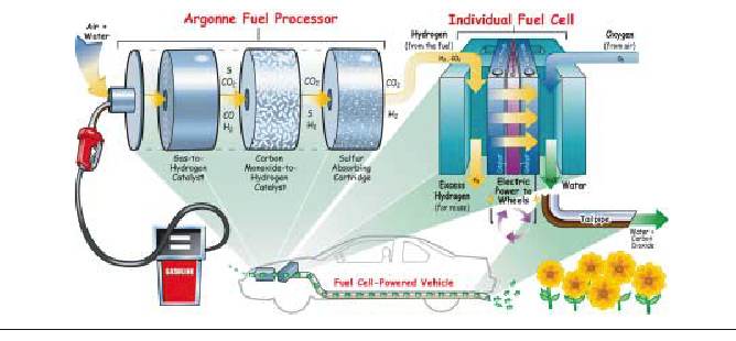
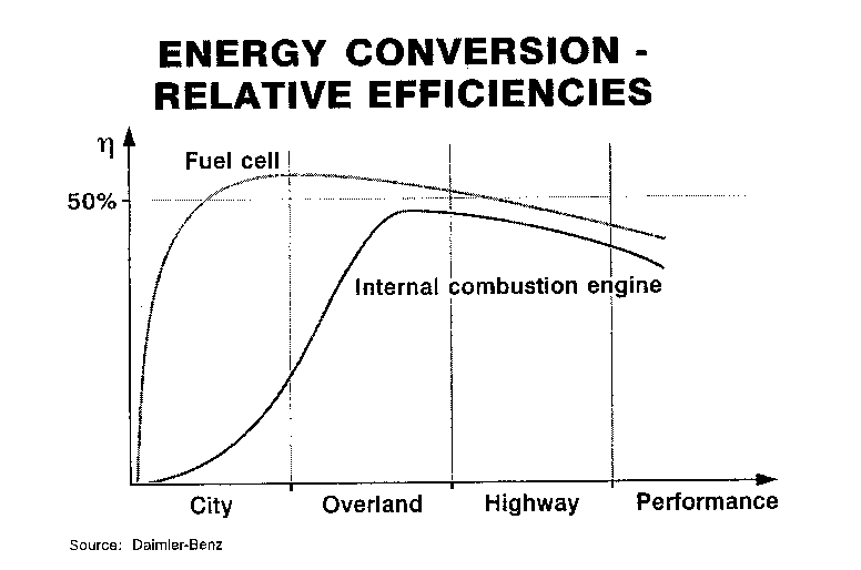
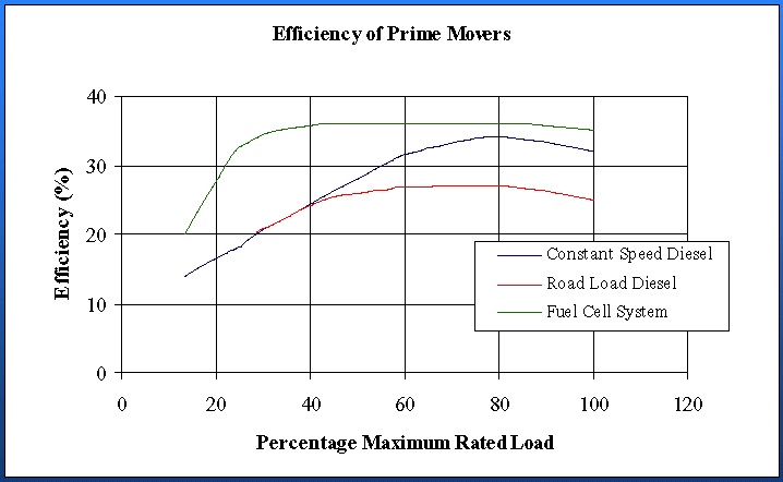
The hydrogen van fleet in Hamburg (Hydrogen Energy Network: Rutherford Appleton Laboratory,10.July.2002)


